Proof of concept
Proof of Concept
The platinized nickel-coated stainless-steel cathode produced hydrogen in our proof-of-concept experiment, while the Ni 0.9Co0.1(OH)2 anode was oxidized to Ni0.9Co0.1OOH in a 5 M KOH aqueous solution (pH 15). The anode employed was a Ni0.9Co0.1(OH)2 anode with a regenerated capacity of 5 Ccm-2. At a current density of 50 mA cm-2, the hydrogen generation stages were carried out for 100 seconds at ambient temperature (without heating or cooling). We set the applied cell voltage to be no more than 120 mV higher than the thermoneutral voltage (1.48 V).
This reduced heat loss and prevented oxygen formation and anode overcharging, which may have caused NiOOH to transition from the -phase to the -p phase. For this quantity of charge, the Faradaic efficiency of the anode charging reaction was 99.2 % based on dissolved oxygen readings. During the hydrogen generation (charging) processes, the cell voltage, Vcell, and anode potential, Eanode, were recorded and are shown in Fig. 3a.
The charged anode was removed out of the cold cell and placed in a hot (T=95 °C) electrolyte (5 M KOH) for 100 s after each of the 100-s hydrogen-generating phases to promote spontaneous oxygen release and regeneration of its starting condition. During the anode regeneration process, significant bubble (O2) formation was detected, but bubbles (H2) were only created on the cathode during the hydrogen generating step.
During each of the charging phases, the cell voltage and anode potential grew consistently, with little variation from cycle to cycle and no continuous drift (Fig. 3a). The anode's SOC returns to its initial state with no quantifiable change at the end of each cycle, indicating that the process is cyclable and does not degrade. Ex-situ microstructural (SEM) and crystallinity (X-ray powder diffraction) investigations were performed before, during, and after the Dual-TCE cycles to demonstrate this. The anode potential ranged from 1.37–1.45 V RHE during the hydrogen generation stages (Fig. 3a), which is substantially below the OER potential of both the Ni0.9Co0.1(OH)2 and NiFe LDH anodes.
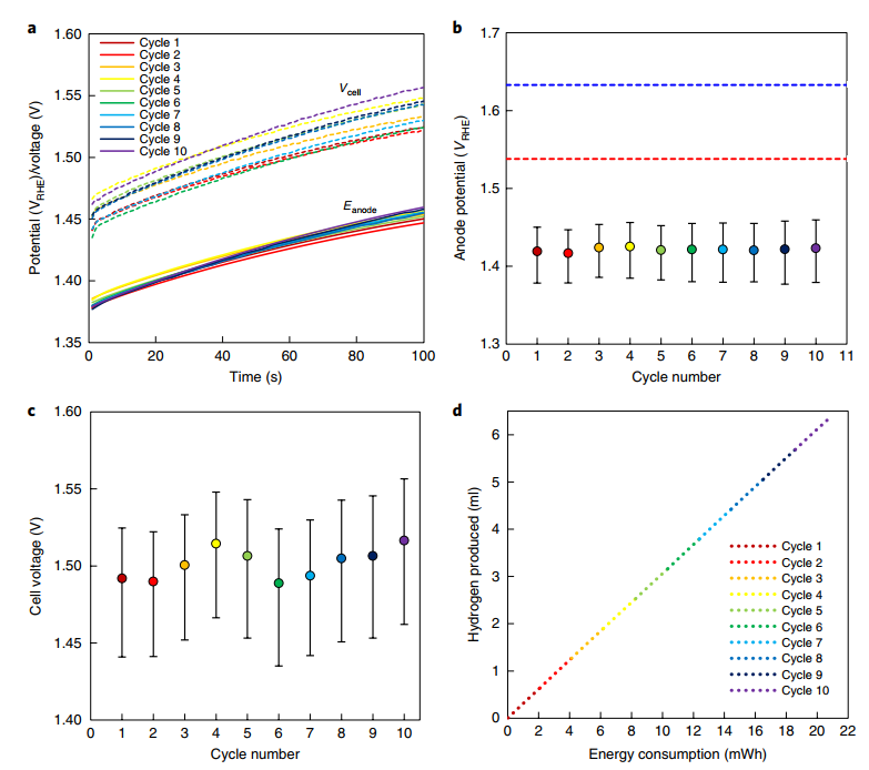
Oxygen evolution is limited at these potentials. Overall, the cell voltage ranged from 1.44 to 1.56 V (Fig. 3a), with an average of 1.5 V over all ten cycles (Fig. 3c). For all 10 cycles, the voltage efficiency of the Dual-TCE process, where Vth is the thermoneutral voltage of the water-splitting reaction (1.48 V under typical conditions), averaged 98.7%. Based on the current and cell voltage measured during the cycles, as shown in Fig. 3d, 6.4 ml hydrogen (at 1 atm and 25°C) was created during the ten cycles given in Fig. 3, requiring 20.8 mWh.
Initially, similar measurements were performed with notional current densities ranging from 10 to 200 mA cm-2. At 10 mA cm-2, the average cell voltage increased to 1.44 V, and at 200 mA cm-2, it increased to 1.60 V. In these measurements, the anode potential was lower than that of the NiFe LDH benchmark anode, indicating that our Dual-TCE technique has a higher electrochemical efficiency than alkaline electrolysis with a state-of-the-art water oxidation catalyst. Second, 100 cycles were performed at the same nominal current density (50 mA cm-2) as illustrated in Fig. 3, demonstrating stable, long-term operation in alkaline solutions.
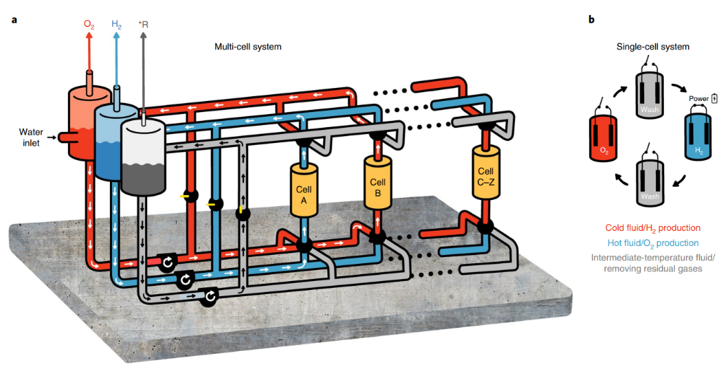
Fig. 4 | Schematic of the multi-cell Dual-TCE process.
A: General electrolyte flow in the process, showing the cold electrolyte circulating in cell A, generating H2 gas that is phase-separated in the middle (blue) tank on the left, while the hot electrolyte circulates in cell B, generating O2 gas that is phase-separated in the red tank on the left. The intermediate-temperature wash fluid in the grey tank on the left is circulated through a bypass most of the time. This fluid is used to ‘push’ the cold and hot electrolyte solutions to their respective tanks at the end of the H2 generation or O2 generation steps. B: Single-cell cycle, showing the regenerative operation in each cell, where H2 is generated under an electric bias at ambient temperature, and O2 is generated at a hotter temperature without applying electric bias (open circuit). *R, residual gases.
Dual-TCE Water Splitting in Carbonate-Buffered Solutions
So far, the proof-of-concept experiments have been conducted in a concentrated alkaline solution, which may be unsuitable for some applications where highly caustic conditions are not tolerated. Because of the lower balance of system costs associated with operating at extreme pH values and the possibility of using low-purity water sources, the option to lower the solution pH to less dangerous levels is advantageous for low-cost implementation. By working in a carbonate–bicarbonate (3:2 ratio of K2CO3:KHCO3) buffer electrolyte with a pH of 10.6, we illustrate the adaptability of our technique. At a nominal current density of 25 mA cm-2, the anode potential ranged from 1.43–1.50 V RHE in this test. This demonstrates that the Dual-TCE water-splitting method is not confined to alkaline solutions and that it has the potential to be used in a wider range of electrochemical applications.
Initiatives Towards Scale-Up and Deployment
The results of our proof-of-concept experiment (Fig. 3) and the additional tests show that the Dual-TCE water-splitting process has the potential to produce high electrochemical efficiency at a wide range of current densities and under a variety of operating conditions while ensuring safe operation with no H2/O2 crossover. We envision a multi-cell system, as shown in Fig. 4a, to turn this process into an operational prototype system that produces pure hydrogen and oxygen gas streams.
Unlike the previous proof-of-concept tests, this system uses a swing design with stationary anodes and cathodes in each cell. A low-temperature electrolyte runs through cell A during hydrogen production, transporting hydrogen bubbles to the hydrogen separator.
A hot electrolyte runs through cell B at the same time to regenerate the (already charged) anode, creating oxygen and transporting the oxygen bubbles to the oxygen separator. The entire system consists of only hot and cold moving electrolyte solutions, with no moving electrodes. To avoid mixing of the hydrogen-saturated (oxygen-saturated) electrolyte with the hot (cold) electrolyte during the switch between cycle steps, an intermediate temperature fluid will be utilized to displace the cold (hot) electrolyte within each cell into the suitable separation tank. The cycle that every single cell goes through is depicted in Fig. 4b, which shows that the intermediate displacement fluid fills the cell between the cold and hot steps. Furthermore, as indicated in Fig. 1b, the electrodes are only connected to a renewable power source during the hydrogen production stage, as illustrated in Fig. 4b.
The system will be sealed up, allowing for the production of high-purity hydrogen and oxygen streams. Furthermore, by lowering the risk of gas mixing, the proposed concept is made safer by the temporal separation of hydrogen and oxygen synthesis in each cell. Finally, as illustrated in Fig. 4a, the system is designed to comprise numerous cells, with some cells creating hydrogen and others producing oxygen at any given time. The findings of the energy and heat balance shown in Fig. 3 only reflect the electrical energy consumption during the first stage of the Dual-TCE cycles, which is performed at ambient temperature without heating.
The anode is heated to 95°C in the second phase to speed up the anode regeneration reaction. This causes some heat loss in our process's overall energy balance. However, because the first step in the Dual-TCE process is endothermic for Vcell1.56 V and the second step is exothermic, the heat loss caused by swinging between the cold and hot steps can be reduced by careful heat management and thermal insulation of the hot components, as well as increasing the anode's capacity so that the heat released during O2 generation compensates for any other minor heat loss. This heat loss is expected to add no more than 2 kWh kg-1 H2.
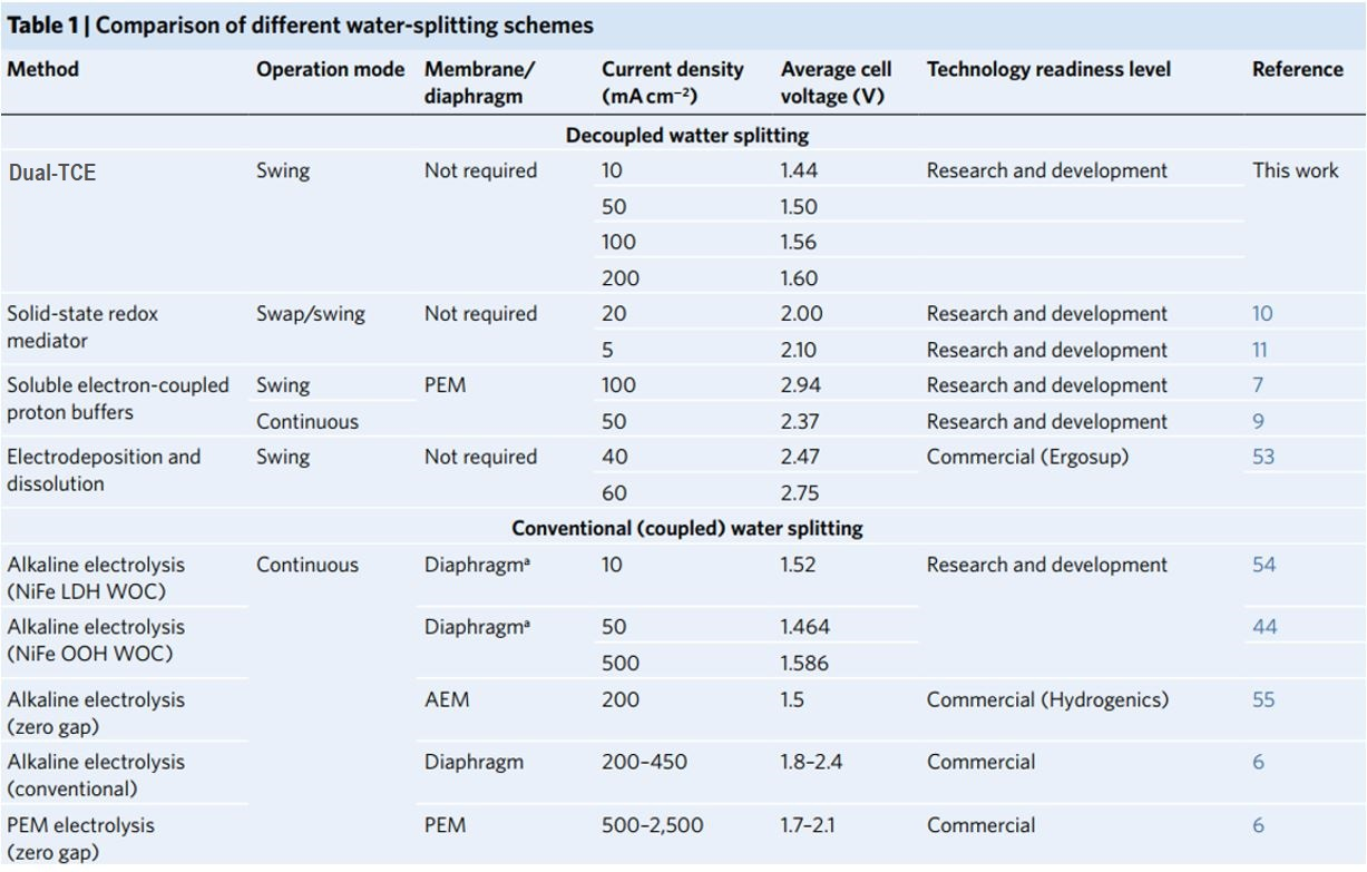
No diaphragm was employed in the reported tests. AEM, anion exchange membrane; WOC, water oxidation catalyst. Operating parameters and electrochemical efficiency (average cell voltage) are shown for landmark reports on decoupled water splitting, alkaline electrolysis with champion catalysts, commercial alkaline electrolysers and PEM electrolysers
The Benefits of the Dual-TCE Approach
In a membrane-free cell, our Dual-TCE technique separates water, creating hydrogen and oxygen in temporally independent steps. Membranelles electrolysis has numerous general advantages over traditional water electrolysis as a result of this. Low material and assembly costs are a result of reduced device complexity; high tolerance to impurities in the electrolyte and adverse operating conditions, which typically foul membranes; and the ability to operate in non-hazardous buffer solutions, which increases operational safety while allowing the use of low-cost catalyst and/or construction materials.
In proton exchange membrane (PEM)/alkaline electrolysis, the problem of H2/O2 crossover across the membrane/separator is overcome in our technique, paving the way for partial-load water splitting and high-pressure hydrogen production. The Dual-TCE technique is also known for its excellent efficiency. We were able to reduce the anode potential to a level competitive with the best-reported water oxidation catalysts by tackling the four-electron OER with single-electron oxidation events of nickel hydroxide and dividing water oxidation into separate one-electron electrochemical and thermally activated chemical steps. It's also worth noting that the Dual-TCE process has far greater efficiency than prior studies that used the Ni (OH)2/NiOOH redox pair as an auxiliary electrode to decouple the water oxidation and reduction reactions.
This is because, in our technique, oxygen is created naturally at our modified anodes by reacting Ni (OH)2/NiOOH with water, with no need for electrode polarization from an external power source. Previously, oxygen was created electrochemically at a conventional anode by polarizing the anode while the Ni (OH)2/NiOOH auxiliary electrode discharged, according to earlier findings. Water penetration to NiOOH sites is enabled by our anode design, and the addition of cobalt enhances electron and proton conductivity while cathodically altering the Ni+2/ Ni+3 redox potential, allowing this chemical to take place. A prior paper described a method that combined electrochemical and chemical reactions. It employs a molecular redox mediator that functions similarly to our Ni (OH)2/NiOOH anode.
The use of a solid redox mediator (the Ni (OH)2/NiOOH anode) eliminates the requirement for a membrane by preventing charged species from transferring between the anode and the cathode. Furthermore, the soluble redox mediator acts in an acidic environment, necessitating the use of rare-earth catalysts like platinum. Our solid redox mediator, on the other hand, works in alkaline solutions, allowing for the employment of low-cost, Earth-abundant catalysts. Finally, our method replaces the traditional water oxidation reaction, which has a higher overpotential than proton reduction, resulting in higher efficiency than previously reported. Table 1 compares the electrochemical efficiency (cell voltage) of our Dual-TCE process to that of earlier seminal studies on decoupled water splitting, as well as alkaline electrolysis employing champion catalysts, commercial alkaline electrolyzers, and PEM electrolyzers.
Our anodes now have nominal current densities of up to 200 mA cm-2, which is at the low end of commercial alkaline water electrolyzer performance. Higher current densities necessitate further refinement of the anode production process and the use of high-surface-area substrates. It is worth noting that making an indirect comparison between our anodes and electrolysis anodes is challenging because the Dual-TCE process takes place throughout the volume of the active Ni 0.9Co0.1(OH)2 layer, whereas electrolysis just involves the surface of the water oxidation catalyst. Using the identical substrate and measurement conditions, a direct comparison with a benchmark water oxidation catalyst (NiFe LDH) reveals that our anode's operation potential is lower than that of the water oxidation catalyst (Fig. 3b).
Conclusion
With the increased use of intermittent renewable energy around the world, effective and viable methods of storing excess energy will become more significant. Our Dual-TCE technique, when combined with renewable energy systems, demonstrates that water splitting under almost thermoneutral circumstances is conceivable, and we highlight several options that can be explored to improve this process. Designing optimum anode materials can increase electrochemical characteristics and diffusion kinetics, as shown here by the inclusion of cobalt. These anodes can be modified to withstand high pressures, allowing for pressured hydrogen production. When combined with a fuel cell system, this leads to applications for electromobility in transportation refueling stations, chemical synthesis, and energy storage. We further show that our method is tolerable to carbonate-containing electrolytes at moderate pH levels, which are far less dangerous than a strong KOH solution. Furthermore, in a comparable membrane-free cell, CO2 reduction can be combined with anode oxidation, with the added benefit of improved product separation by geographically and temporally isolating CO2 reduction from oxygen generation. Approaches like these pave the way for electrolytic chemical production that uses less energy.